Quartz Scintillator Target Insert
- Model #: BPV-24.F
- Last modification: Jan/12/2018
contact us about this product


The scintillator assembly shown in Figure 1 is a beam diagnostic device primarily used during the commissioning of the beamlines. The scintillators can be used at other times for the purpose of ion-optic problem solving, beam studies on beamline, or for determining extracted beam characteristics at the exit ports for negative hydrogen cyclotrons prior to beamline or target design.
Features & Applications
The scintillator assembly is mounted in the target selector assembly at the downstream end of the beamline. A charged-particle beam current less than 3 micro-amperes at 14 MeV kinetic energy can bombard the scintillator. At the location where the beam impinges on the quartz scintillator, the quartz will scintillate, emitting visible light that can be observed with a CCD Camera and observed on a CCTV monitor or it can be observed on a laptop as a “live action” image.
The scintillated beam spot is assumed to be roughly linear with beam intensity. By observing and recording the scintillated image as a function of accelerator settings (ion source, Main magnet, RF, stripper, vacuum) or beamline settings (XY Steering Magnet, Quadrupole Magnets), the operator can determine beam size, shape, and centring as a function of the accelerator or beamline settings.
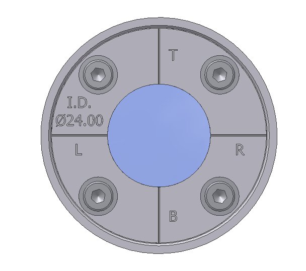
Typically the operator is interested to determine what combination of settings best provides a centred and circular beamspot that is the diameter of the nominal target aperture. The scintillator holder as shown in Figure 2 has cross-hairs scribed into it with lettering T = Top, L = Left, R = Right, B = Bottom, so that the orientation and location of the beamspot can be ascertained. The scintillator holder aperture is accurately machined to a diameter of 24.00 mm, so that image analysis software used to analyze the recorded beamspot images has an accurate feature within the image which can be used to calibrate length scale.
Technical Performance Characteristics:
|
Maximum Beam Power: |
42 Watts |
|
Maximum Current for 14 MeV Proton: |
3 Micro-Amperes |
|
Maximum Exposure Time at Maximum Beam Power: |
2 Hours |
|
Assembly Aperture for Optical Calibration: |
∅24.00 mm |
|
Cross-Hair Scribe Line Orientation: |
Top, Left, Right, Bottom |
Interface Technical Specifications:
|
Scintillating Material: |
Quartz, 19 mm by ∅32 mm |
|
Operational Vacuum Region: |
High Vacuum (~10-6 Torr) |
|
Vacuum Seal: |
O-Ring |
|
Mounting Arrangement: |
Mount in Target Port in a TRIUMF type Target Selector, or custom arrangement |
|
Recommended Viewing Arrangement: |
45 Degree Mirror† to CCD Camera*†. Image capture by Personal Computer with frame grabber capabilities† |
|
Data Analysis: |
Image Analysis software such as Optimetric†. |
See figure 3 for basic set up.
*The camera is not placed directly in line with scintillator on the charged particle beam axis, since this will maximize neutron damage to the camera. Even with the camera located at 90 degrees to the beam axis there will be neutron damage to the CCD camera pixels almost immediately upon beam bombardment. The useful life of the camera is on the order of 2 hours. Choose a basic CCD camera with no advanced processing circuitry or printed circuit boards for advanced special features as this circuitry may fail quickly in the neutron fields.
†These devices and software can be provided with the scintillator assembly or not, depending on your requirements.